WAVE TRAP
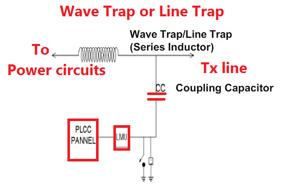
Wave trap is used to create high impedance to the carrier wave high frequency communication entering in to unwanted destinations typically substation. Carrier wave communication uses up to 150kHz to 800kHz frequency to send the all the communication. These high frequency damages the power system components which are designed to operate 50 or 60 Hz. Wave traps are also called as line traps.
Wave traps are connected in series with power line and thus their coils are rated to carry the full line current. The impedance of a line trap is very low at the power frequency and will not cause any significant voltage drop.
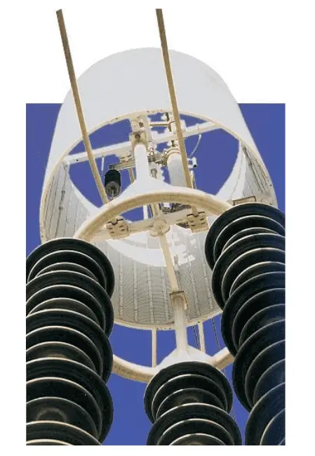
Internal View of Wave Trap

CONSTRUCTION

Wave trap circuit consists of three major components such as.
- Main Coil
- Tuning Device
- Protective Device
Main Coil

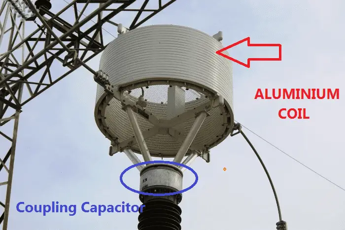
- Main Coil is an outer part of the wave trap circuits and which is made from standed aluminum cable.
- There are number of circular layers in main coil which are separated by a cooling duct between them to avoid overheating.
- The coil carries rated continuous power frequency currents, therefore this is the power inductor in this system.
- It provides a low impedance path for the electricity flow.
According to following equation,

When the frequency increases, the inductive reactance will get increases. Hence it creates high impedance for high frequency signal and low impedance for low frequency signal.
This unit prevents the high frequency carrier signal from entering the power circuits.
Coupling Capacitor:
It is used to receive high frequency communication signal. Capacitor creates low impedance for high frequency signal.

As the frequency increases, the impedance value decreases and the frequency decreases the impedance increases.
No comments:
Post a Comment