Power Line Carrier Communication
Use of PLCC in modern electrical power system is mainly for Telemetry and Telecontrol. Tele means remote. Telemetry refers to science of measurement from remote location
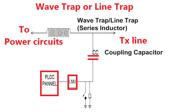
The following figure shows a basic PLCC network used in power substations. The Power line carrier Communication (PLCC) uses the existing power infrastructure for the transmission of data from sending to receiving end. It works in full duplex mode.
PLCC system consists of three parts:
- The terminal assemblies include the receivers transmitters and protective relays.
- The coupling equipment is the combination of line tuner, coupling capacitor and the wave or line trap.
- The 50/60 Hz power transmission line serves as path for relaying data in the PLCC bandwidth.
Network Diagram

Main Parts of PLCC System
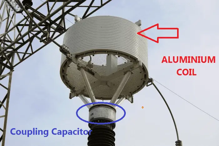
Coupling Capacitor
- It forms the physical coupling link between transmission line and the terminal assemblies for the relaying of carrier signals.
- Its function is to provide high impedance to power frequency and low impedance to carrier signal frequencies.
- They are usually made up of paper or liquid dielectric system for high voltage application.
- The ratings of coupling capacitors range from 0.004-0.01µF at 34 kV to 0.0023-0.005µF at 765kV.
Drain Coil
The purpose of drain coil is to provide high impedance for carrier frequency and low impedance for power frequency.
Line Tuner
- It is connected in series with the coupling capacitor to form a resonant circuit or carrier signal frequency high pass filter.
- Its function is to match the impedance of the PLC terminal with the power line in order to impress the carrier frequency over the power line.
- It also provides isolation from power frequency and transient over-voltage protection.
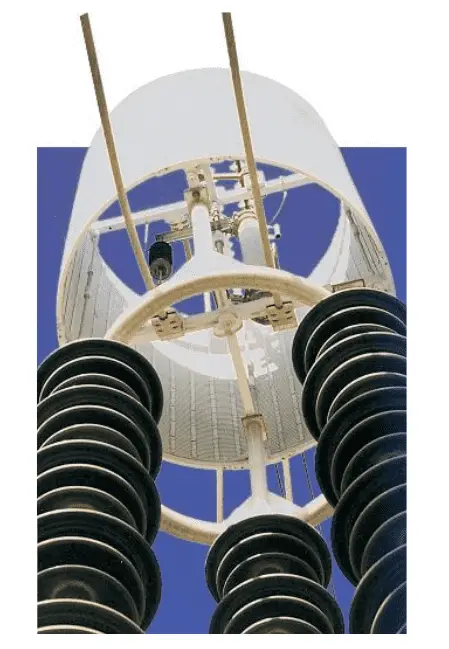
Line Trap or Wave Trap
- It is a parallel L-C tank filter or band-stop filter connected in series with the transmission line.
- It prevents high impedance to carrier signal frequencies and very low impedance to the power frequency.
- It also prevents unwanted loss of carrier signal power and prevents carrier signal transmission to adjacent power lines as well.
- It consists of following parts:
Main coil
An inductor that is connected directly to the high voltage power line carries power frequency.Tuning device
It may be a capacitor or a combination of capacitor, inductor and resistor, connected across the main coil in order to tune the line trap to the desired blocking frequency.Protective device
It is usually a gap type surge arrester used to protect the line trap from damage due to transient over-voltages.
Power Line Channel Characteristics
Characteristic Impedance
- The characteristics impedance of transmission line is given by :
Where, L = the inductance per unit length in Henry(H).
C = the capacitance per unit length in Farad(F).
It varies in the range of 300-800 Ω for power line communication
Applications
Protective Relaying
For the purpose of carrier aided protection, PLCC channels use modulation schemes namely the Amplitude modulation(AM) for blocking schemes and Frequency Shift keying(FSK) for unblocking, permissive and direct-trip schemes.Telemetry
It is used to monitor electrical quantities like voltage, current, power etc. at remote locations.Telephony
Voice messages are sent over SSB narrow band mode with bandwidth ~3khz.Home Automation and Home Networking
Using low voltage electrical network at home to control appliances by sending or receiving data through power line.
Video Animation
https://www.youtube.com/watch?v=2ieGFgfDOxA


